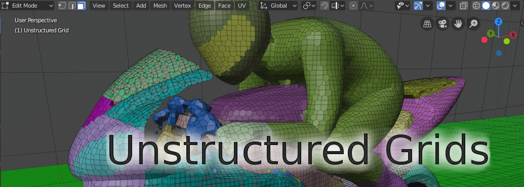
Unstructured Grids Addon for Blender
Introduction
Unstructured Grids (UG) is an add-on for Blender for creating, importing, editing and exporting of 3D finite volume meshes composed of arbitrary polyhedron cells (a.k.a 3D unstructured grids. The motivation for this work was the lack of open source volume mesh editors. There are numerous finite volume mesh generators, but practically no general or visual editors.
Add-on only handles volume mesh topology and geometry (the definition of cells). Field data (cell data or point data) for the mesh is disregarded. Supported volume mesh operations include moving of selected vertices, deletion of existing cells, extrusion of new cells, and assignation of selected faces and cells to named boundaries and zones. The user of the add-on is assumed to know Blender modelling and material systems on a basic level.
Warning
This add-on is experimental. There are no guarantees. Use at your own risk. Always check the resulting exported mesh before use in simulations.
Main Features and Limitations
Many operations are slow for large meshes. This is due to the fact that volume meshes are not natively supported in Blender. Therefore cell and face information related to unstructured grids are kept in separate Python object data model, which is slow.
Internal faces and internal edges are not shown in Blender. Boundary faces and all vertices are visible in Edit Mode.
Unstructured grid is defined by lists of cells, cell faces and face vertices. Cell description is compatible with OpenFOAM PolyMesh description, including named boundary faces (patches), and cell and face zones. Import and export is provided also for VTK Unstructured Grid (.vtu) XML ASCII file format.
Supported native Blender operations include moving of vertices, assigning materials to faces (boundary patches) and assigning vertices to vertex groups (zones). Otherwise, modifications of unstructured grids rely on special operators (‘UG’ in operator name) which keep the cell data and Blender mesh object in sync.
New cells can be created by extrusion from any face selection.
Unstructured grids with overlapping baffles (=overlapping boundary faces defined by shared vertices) or split baffles (=overlapping boundary faces using duplicated vertices) are not supported.
Tested on Blender LTS version 3.6.
Installation
Add-on code is available at https://github.com/tkeskita/unstructured_grids. To download add-on from Github, Select “Code” –> “Download ZIP”.
Start Blender, go to “File” –> “User Preferences” –> “Add-ons” –> “Install” –> open the add-on zip file.
Activate the “Unstructured Grids for Blender” add-on in Preferences. Add-on is located in Mesh category.
Note
Python Logging messages (printed to terminal if Blender is started from a terminal) may be useful in case of problems. For more information take a look at file __init__.py.
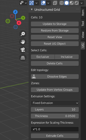
UG Toolbar
Add-on is visible in Blender’s 3D Viewport in Sidebar as a separate tab. To view the add-on panels, you must
Select a mesh object (in 3D Viewport or in Outliner)
View Sidebar (“View” –> “Toggle Sidebar” or press “N” key in 3D Viewport)
Select “UG” tab in the Sidebar
Note that if no unstructred grid has been imported or created by extrusion from a face selection, then most of the tools are inactive.
Unstructured Grid Object
Import and Extrude Cells operators (see below) create a Blender Mesh Object called Unstructured Grid, to contain the unstructured grid. Add-on ignores all other Blender objects.
Import and Export
You can import and export unstructured grid via menu commands File -> Import/Export. Add-on supports currently two types of volume mesh formats:
OpenFOAM PolyMesh: OpenFOAM’s PolyMesh ASCII format (see PolyMesh description). Select the polyMesh directory -> OK.
VTK Unstructured Grid (.vtu): Unstructured Grid (.vtu) XML ASCII file format. Note: Export currently creates VTK polyhedrons.
Extrusion of New Cells
Extrude Cells operator creates new cells from face selection based on Extrusion Settings shown on the Toolbar. To extrude cells, first select one or more faces in the Unstructured Grid object (or any mesh object for first extrusion), then run Extrude Cells operator by clicking on the named button in the toolbar. Extrusion settings include:
Extrustion Method drop-down menu lists options for available extrusion methods:
Fixed Extrusion Method is the most basic method. New cells are created by extruding each selected face vertex towards the vertex normal direction. Total vertex extrusion length is equal to Thickness. No checks for result quality or possible intersections are made.
Shell Extrusion Method is a more advanced method, meant for addition of flat cells (boundary layer cells) on top of an existing surface mesh. This method extrudes each selected vertex in a direction, which is iteratively adjusted using surrounding vertex extrusion directions. The aim of this method is to apply an extrusion direction which reduces the risk of creating intersections near convex shapes.
Warning
This method may create highly non-orthogonal or skewed faces. The method will create intersecting faces for highly convex shapes and shapes where two extrusion fronts meet, if extrusion thickness is too large (depends on the case).
Ensure Layer Thickness option scales extrusion length for the Shell Extrusion Method so that the layer thickness specified in the Thickness option is approximately reached. This option may cause increase of layer thickness for convex shapes. If this option is disabled, then total vertex extrusion length is equal to Thickness.
Interactive Correction creates a temporary Interactive Correction object, before actually extruding the cells, so that the user has a possibility to manually alter the extrusion directions (vertex locations) for vertices. When the locations have been edited in Blender, run Finish Extrude Cells to proceed with the actual cell creation.
Check for Intersections enables intersection detection for interactive correction. Intersections can occur when extrusion directions of adjacent vertices cross each other. This happens when extrusion thickness is too large for the Shell Extrusion Method. There is no definite value for when intersections start to occur. If this option is enabled and intersections are detected, a warning is issued in Blender info text (text shown in Blender bottom bar), and intersecting vertices are selected (highlighted in Vertex Select Mode).
Note: Intersections are currently detected only for extrusion top faces (but not for side faces).
The intersection detection algorithm casts rays from numerous starting points slighly away (perturbed locations) from each vertex towards neighbour vertices. Intersection is assumed to occur if a ray hits a non-neighbour face. The perturbation length (how far away ray casting start point is from current vertex) is calculated from the mesh as: maximum bounding box side length, multiplied by Perturbation Factor. For example, a Perturbation Factor value of 0.0001 means that if maximum bounding box side length for the mesh is e.g. 10 m, then vertex location is perturbed by 1 mm in the intersection detection.
Perturbation Factor determines the perturbation length scale factor for the intersection detection algorithm (see above). The value of Perturbation Factor affects the accuracy of the intersection detection, so you may try to change this value if the result of intersection detection is bad.
Hyperbolic Extrusion Method is a highly experimental extrusion method which is neither documented nor supported. Do not use, for development and testing purposes only.
Layers specifies the number of cell layers for extrusion
Thickness specifies the total length of side edges for extruded cells, or target height for all of the extruded cell layers.
Expression for Scaling Thickness allows user to specify a Python expression which scales Thickness for each layer. x in the expression is layer thickness. The default value x*1.0 will keep thickness constant.
Create Trajectory Object will optionally create an additional trajectory object, which contains the vertex extrusion edges only, for debugging purposes.
Note: Boundary vertices are always extruded in the vertex normal direction.
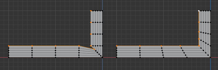
The following image illustrates the difference between the Fixed Extrusion (on left) and the Shell Extrusion (on right) methods:
Storage and View Operators
The top part of the Unstructured Grid Toolbar shows current number of cells, or a warning if there are no cells defined.
Update to Storage takes all changes made to the Unstructured Grid Object, and stores them in text storage variables. This allows saving of a snapshot of current status in work memory. This operator is run automatically when .blend file is saved.
Restore from Storage discards Unstructed Grid Object and rebuilds it based on the information in the storage variables. This operator is run automatically when .blend file is opened.
Note
You can use Update to Storage and Restore from Storage commands as a rudimentary one-step undo operation. Using Blender’s Undo command (CTRL-Z) is unfortunately not currently supported.
Reset View refreshes the view. It shows boundary faces and hides deleted faces and vertices.
Cell operations
Cell selection is based on vertex selection. You can first select any vertices of the Unstructured Grid Object in Vertex Selection Mode in Edit Mode. Then select operator:
Exclusive will reduce current vertex selection to whole cells. If vertex selection does not include all vertices of any one cell, then vertices are deselected.
Inclusive will extend current vertex selection to cover whole cells. If selected vertex is part of any cells, then all other vertices of those cells is added to vertex selection.
Delete Cells will remove whole cells included in vertex selection. Deletion of cells creates new boundary faces, which are added to default material (boundary patch, see below). Note: Cell deletions are not displayed correctly in Object Mode.
Inside Object Name specifies an object name for the Select Verts Inside operator. This operator adds all vertices which are located inside the outward facing polygons of the specified object to selection. Polygons are assumed to form a closed volume. This operation is useful for creating cell zones.
Edit topology
Dissolve Edges merges selected vertices which are connected by edges in pairwise manner. TODO: Experimental, needs to be improved.
Shrink Boundary moves vertices of selected faces “inwards” towards vertex normal direction by a distance specified in Shrinking Distance. Note: Highly experimental feature, needs improvement.
Zones
Zones are essentially an additional list of faces (internal or external) or cells in OpenFOAM. Zones are used to control subset of faces/cells in simulations. Note: VTK unstructured grids do not currently support zones.
Zones are specified by assigning vertices to Blender Vertex Groups. Vertex group naming defines zone type. Cell zone x must be named as cellZone_x, and face zone y must be named as faceZone_y.
Update from Vertex Groups operator must be run after assigning vertices to vertex groups to update changes to unstructured grids.
If any face zones exist, then following additional options become visible:
Edit Face Zone Orientation is a number, which specifies which face zone will be affected by the following operations:
Start Editing will create a temporary Face Zone Orientation Object (which contains only the faces of the face zone), switch on Edit Mode and Face Orientation Overlay, which colors faces to blue (face normal towards view) or red (face normal away from view). In this mode, the user can select faces and flip their normals if needed (by using the Flip Face Orientations operator), to harmonize all face normals. Harmonizing is needed to get e.g. correct face flux sums in OpenFOAM simulation for face zones.
Finish Editing will exit the normal editing mode, transfer information of faces whose normals need to be flipped (flipMap) back to Unstructured Grid Object, and finally delete the temporary Face Zone Orientation Object.
Info About Selected Items
These operators show information for debug purposes.
Modification of Boundary Patches
Each boundary face of the volume mesh is assigned to a named list, called boundary patch in OpenFOAM terminology. This allows specification of boundary conditions for simulations. All boundary faces must belong to one (and only one) boundary patch. The add-on uses Blender`s Material System to visualize and specify boundary patches. The material name is used as patch name.
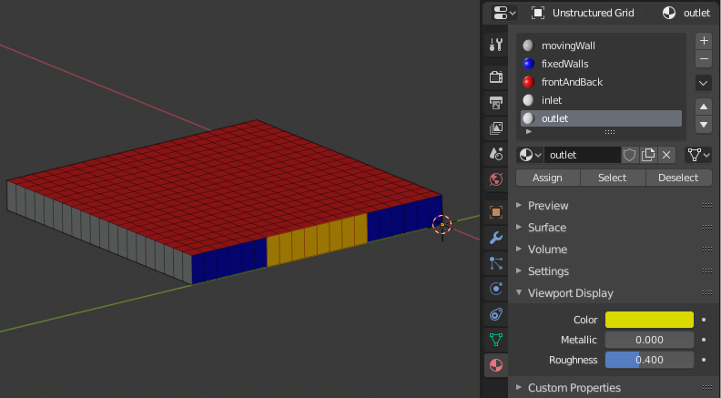
To assign faces to materials (patches), you must select faces (using Face Selection Mode in Edit Mode), select or create new material, and the click on Assign button.
Transformation of mesh vertices
Blender has a powerful system for selecting vertices and operating on selections (e.g. moving, rotating or scaling) in 3D Viewport. Blender also supports inputting exact measurements for operations. This makes it possible to edit volume meshes (without topology changes) in Blender simply by moving vertices.
Note
Direct deletion of vertices or faces from Blender Mesh Object is not supported. Only Delete Cells operator can be used to keep Blender Object in sync with the Python cell data model.
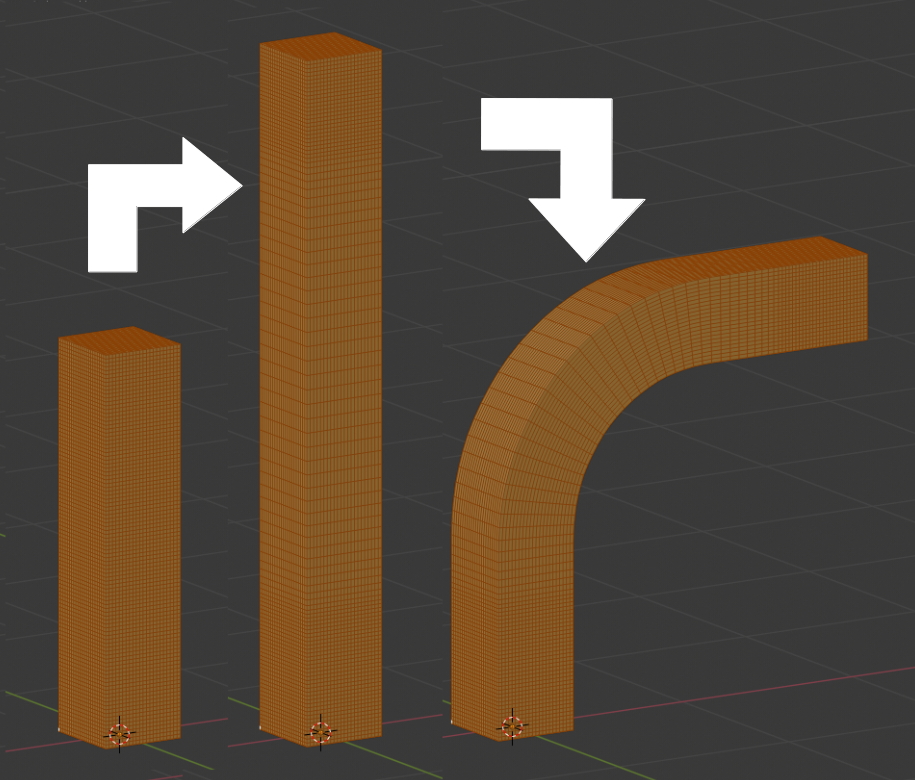
The add-on can be applied for tasks like elongation/stretching of cells (by using Proportional Editing in Blender), or curving simulation domain, to model e.g. pipes (by applying Curve Modifier in Blender)
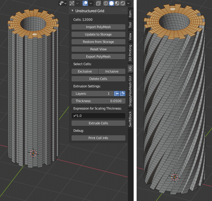
Another example shows extrusion of a mesh profile (on left), followed by twisting of the result (on right):
Example
A modified example of the OpenFOAM cavity tutorial mesh is located in the examples folder in the add-on sources (file name cavity.blend).
OpenFOAM Export Workflow
Export volume mesh from Blender (File -> Export -> OpenFOAM PolyMesh (UG)) into an empty polyMesh folder (under your OpenFOAM case folder constant/polyMesh).
Run OpenFOAM command renumberMesh -overwrite to optimize bandwidth. This is needed, because order of faces and cells exported from Blender are not optimized in any way, so the resulting mesh may be inefficient for numerical solution.
Run OpenFOAM command checkMesh to make sure mesh does not contain errors.
FAQ
Q1: I get an error like this when importing a polyMesh:
IndexError: bpy_prop_collection[index]: index 123 out of range, size 123
A1: Your mesh most likely contains overlapping baffles or split baffles. Unfortunately those are not supported by this add-on. You can try to run OpenFOAM command mergeBaffles to remove the baffles, if that is an acceptable option for you.
Help and Feedback
Please use GitHub issues for requests, discussion and feedback: https://github.com/tkeskita/unstructured_grids/issues
If you use this add-on, please star the project in GitHub!
OpenFOAM Trade Mark Notice
This offering is not approved or endorsed by OpenCFD Limited, producer and distributor of the OpenFOAM software via www.openfoam.com, and owner of the OPENFOAM® and OpenCFD® trade marks.